A Complete Arduino Bathroom Scale
Posted 2016/01/14. Last updated 2016/01/22.
Introduction
One of the nice things about going back home is that I can spend quality time with my dad, working on electronics projects. This time, the project was fixing a digital bathroom scale. Its voltage regulator was burnt, but bypassing it did not work, and the passive components did not seem obviously damaged, so the problem probably originated from the ICs with scratched off markings, or the epoxy blob.
The obvious solution (well, besides buying a new one, but what kind of a solution is that?) was to get rid of the internal components, reuse the case and the sensors, and build everything from scratch. There are some good tutorials out there for this, but they tend to either focus on reverse-engineering the LCD signals (e.g. here and here) or focus on other parts of the circuit such as the output of the ADC converter (e.g. here and here) to get access to the readings, but neither would work in this case, as the scale was non-functional. And those tutorials that actually use the sensors directly tend to be proof-of-concepts (e.g. this one and this one) instead of complete, usable solutions.
As a result, I wanted the end-result to fit in the original casing, and perform the same way as a regular scale, with features such as auto power-off. This write-up explains how the task was accomplished using an ATtiny85, the HX711 Analog-to-Digital Converter (ADC), and a 4-Digit 7-Segment Display driven by the MAX7219 chip, with the code on GitHub per usual. [UPDATE: This project has been featured on Hackaday and Atmel's blog!]
Measuring the Weight
The load cells on digital scales are usually of the strain gauge type, such that their resistance changes based on the pressure/force applied to the device. Usually, this takes the form of a wire (foil) arranged in a zig-zag pattern, such that the variability in the resistance is more sensitive to strain in one of the two directions (vertical/horizontal).
The gauge factor (GF) of the strain gauge quantifies how the resistance changes based on the strain applied. However, the typical changes in resistance are in the order of less than 1 Ohm, so they cannot be measured directly as is. The solution lies in placing the gauges in a Wheatstone bridge configuration, as shown below (image from Wikipedia):
The idea is that applying a fixed, known voltage between two of the terminals (in this case A and C), called the excitation voltage, one can measure the signal voltage between the two other terminals, and if 3 of the resistors are known (and the initial ratios balanced), one can derive the value of the fourth one.
However, the load cell ratings for a full mechanical load are in the order of a few mV per V of excitation, so to accurately measure these changes, one needs a good amplifier and ADC, as the Arduino's built-in 10-bit ADC would not be sufficient for these readings, even using analogReference(INTERNAL) to make the 1024 steps span 0-1.1V instead of the full 0-5V range.
This is where the HX711 chip comes in with its 24-bit ADC and gain of 128. The Arduino HX711 modules sold just require connecting it to the 4 points of the Wheatstone bridge, and then using two Arduino pins: one to provide the clock, and the other to read the data. Though the interface to the HX711 is quite straightforward, I decided to use a library and after calibrating the scale against known weights using the example application, it was time to move on to the other parts of the circuit.
The Display Module
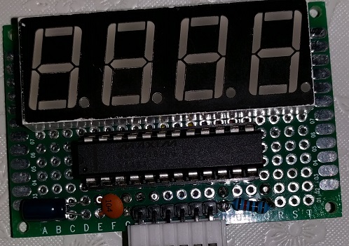
Though I had verified that the original display of the scale still works, I decided against using it, as the LCD had 20 pins, and reverse-engineering it without seeing it in action would be too much of a hassle (though a good project on its own for the future). I instead ended up using a common-cathode, 4-digit, 7-segment display (see here for the pinout), which I drove with the MAX7219 chip by Maxim, exactly as described in the datasheet, but also placing a 10μF electrolytic and a 100nF ceramic capacitor between its VCC and GND. It is worth mentioning that the MAX7221 and the AS100, AS1106, and AS1107 chips are also pin-for-pin compatible with the MAX7219, though I did not test them here. For driving the chip, I used the LedControl library, though with minor modifications for displaying various characters of the alphabet (links to my fork and pull request), and created a dependent library that took care of displaying and/or flashing the desired values and messages. Here is what my modular display looks like:
Completing the Circuit
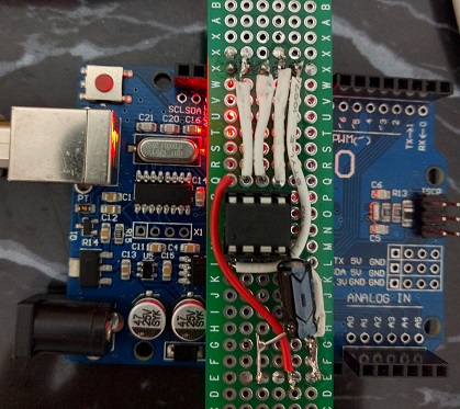
With the two modules ready, and accessible from the libraries, the next step was to connect them through a microcontroller. I went with the ATtiny85, as I like its small form-factor, and did not want to have unused pins. Since I ended up reprogramming the chip a number of times (see here for a tutorial) as I was adding functionality, I ended up creating a board to place on the Arduino UNO to make the job easier:
The ATtiny85 gives access to 5 I/O pins (plus one RESET pin), while we need 2 pins for the scale (SCK, DT), and 3 pins for the display (SCK, DIN, CS), so we need to be a bit smarter to make the scale work and have left-over pins for other functionality. Because the HX711 does not implement the Serial Peripheral Interface (SPI) protocol (it is missing the Chip Select pin), it tries to interpret any transitions on the clock as commands. To overcome this and actually share the clock line, the code powers down the scale before using the display, and then powers it back up with some delay, exploiting the clock pulses that the module expects.
This frees up a pin that we can use to implement the power-off functionality. I did not want a fixed time-limit (which can easily be implemented using capacitors), and I wanted the circuit to turn off completely (as opposed to just entering low-power mode), so I based the circuit on Karl-Heinz Kübbeler's Transistor Tester (manual and long EEVblog discussion). The full schematic for the scale is shown below:
The idea is to have a PNP transistor (I used the S8550) connected to the battery, which is turned on by connecting its base to ground through a regular tactile button switch. This powers the Arduino (through the L7805 regulator), which then sends current to the base of an NPN transistor (the S8050 in this case), essentially connecting the base of the PNP transistor to ground. This allows the circuit to stay on, even when the button switch is no longer pressed, until the Arduino turns the pin off in code, when the readings have been stable for a few seconds.
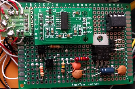
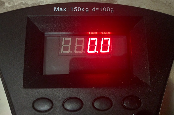
In the end, the display was kept on one PCB (and connected via a pin header and a Molex connector on one end), while the rest of the components were soldered on a separate perfboard by my dad who did a great job placing them in a way that would make everything routing easy. The two PCBs were then separated by cardboard to prevent any short-circuits. The end result can be seen below on the left, with the zeroed scale on the right (which also shows the display surrounded by cardboard to hide all other components).
Future Improvements
Though the scale is fully functional, the truth is that more pins would be welcome to implement more functionality. And even though using an ATmega328P directly is easy, the form factor of the Arduino Nano is probably more convenient, since it consists only of SMD components, can be programmed using its mini-USB interface, and clones are available for about $2.
Regarding the current functionality, it is worth mentioning that the reset pin is connected to a button that turns the scale off, but by burning the fuses appropriately or by using a voltage divider (see this post for an explanation of both options), the pin can be used to reset the tare weight. This was implemented in code, along with the ability to calibrate the scale against fixed weights via long and short presses, and storing the scaling factor in the EEPROM, but the interface was not particularly intuitive and overall I doubt it would be useful, so I ended up removing it.
With more I/O pins, however, the functionality could be improved, for instance with up/down buttons, and the scale could also use the kg/lb switch present in the original. Finally, we would also be able to use the extra pins to implement biolectrical impedance analysis (BIA), which allows estimating the body fat percentage, and for which the sensors are already present on the scale.
Conclusion
Overall, although the code is pretty simple, but I like the fact that the hardware brought everything together, and that the scale behaves exactly like a regular scale, with auto power-off functionality, and also looks like a real scale as it fits in the original space. And though there is plenty of room for additional functionality, it was very educational to see how digital scales actually work, and create what is essentially a full product. And as always, if you want to try it out for yourself, the code, library, and schematics are available on the GitHub repository.


