A Power Switch for Chromecast using Arduino, Bluetooth, and Tasker
Posted 2015/12/24. Last updated 2019/03/23.
Introduction
I've recently started using my first-gen Chromecast with my monitor, and my only complaint is that there is no way to turn it off natively. You either need to disconnect the power, or turn off the TV, but I wanted a way to switch it off from my Android phone, since my monitor does not have a remote. I opted for a solution that uses an Arduino Bluetooth module, and receives commands from its paired device to control the state of the power output to the Chromecast. And because manually turning Bluetooth on, connecting to the Arduino, sending the commands, and then switching Bluetooth back off was not quite as automated as I had hoped, I decided to write a Tasker plugin that would take care of that. This is a detailed write-up discussing some of the design decisions, but the code (and the APK binary) can be found on GitHub in case you want to try it out directly for yourself. [UPDATE: Based on the discussion on Hackaday, it wasn't entirely clear what the purpose of this hack was. To clarify, the Chromecast is permanently connected to a monitor (not a TV) without a remote, and thus the monitor never went to sleep unless I manually removed the Chromecast's power. This was a solution that allowed me to remotely power off the Chromecast, without having to get up and physically do so. FURTHER UPDATE: This post was also featured on Atmel's blog! 17/09/2017 UPDATE: The Tasker plugin now supports using variables for the Bluetooth MAC and the message string, and is published on Google Play].
The Hardware
I wanted to create my project based on hardware that I already had available, so the choice was between the HC-05 Bluetooth module and the ESP-01 WiFi module. In the end, I opted for the Bluetooth option, which requires physical proximity, as I didn't want to connect the ESP8266 to the local WiFi network. This meant that I had to use some sort of microcontroller as well, so I opted for the ATtiny85 instead of a fully-fledged Arduino (even a Nano or Pro Micro), as it is smaller, and with fewer I/O pins.
The main idea is that the ATtiny85 and the HC-05 communicate over serial in order to allow for incoming Bluetooth connections, and to parse incoming messages. Then, upon receiving the right commands, the ATtiny85 switches power to the Chromecast on or off through some transistors. In terms of powering the circuit, since the Chromecast, ATtiny85, and the version of the HC-05 that I have run on 5V, I power them directly from USB, and have the transistors control the connection of the Chromecast to GND, with its VCC always connected. The transistors used are S8050 NPN low-power, high-current transistors which I had handy, but they are probably not the ideal approach, especially considering that in the end I did not use a resistor at the transistors' bases. I placed three of them in parallel, controlled via two ATtiny85 pins (so as not to exceed the 40mA per pin limit), so they should be good for up to about a 2A load. Of course, having isolation between this circuit and the Chromecast would be ideal, but I didn't have any optocouplers, and didn't want to power the circuit separately. The schematic can be seen below:
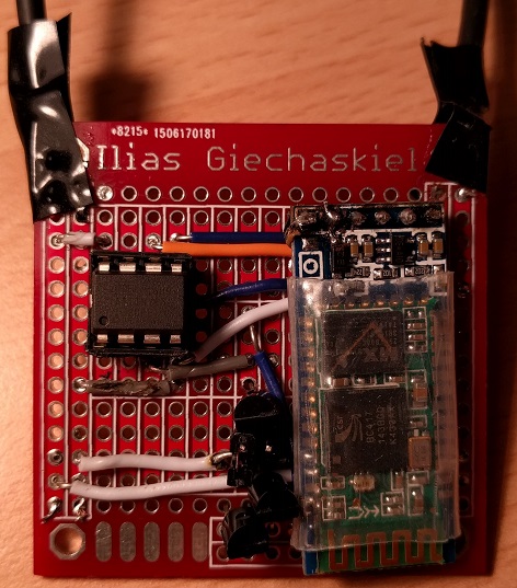
I wanted this project to be my first semi-permanent project, so after some quick testing on a breadboard, I transferred the components to a PCB prototyping board which I had designed a while back (and printed at Dirty PCBs). At the same time, I did not want to tie the ATtiny85 and the HC-05 to the particular project, in case I want to reuse them, so I used a DIP socket, and will be using female headers once they arrive (for now, the module is just "hanging" there). I also have a jumper bypassing the transistors in case I want to permanently supply power to the Chromecast. Finally, I should have probably used USB socket connectors, but I didn't have any immediately available, so I cut a micro-USB cable in half, and soldered both ends on the PCB directly. This is the end result:
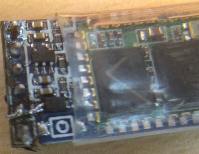
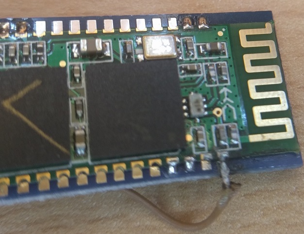
It is worth mentioning that my version of the HC-05 module did not have the KEY pin which is normally connected to the IC's pin 34, and which needs to be a logical HIGH for the commands to work. As a result, I had to manually solder a wire between the EN pin and PIN 34. The dial for my analog soldering iron is also somewhat wobbly, so the temperature ended up damaging the trace of the VCC pin, forcing me to make a localized repair, as can be seen below:
The Firmware
The code itself is pretty straightforward, since the HC-05 communicates with the ATtiny85 over a simple serial connection using AT commands. On boot, the ATtiny85 sends commands (with some intermediate delay) for resetting the HC-05 to its factory settings, and then changes the module's name and pairing PIN code/password. Then it initializes the Serial Port Profile (SPP), and initiates device inquiry, which it immediately cancels, since it does not connect to devices directly, but rather has other devices connect to it. The reasons for initiating the discovery are not entirely clear to me, but I believe that this is how the module becomes discoverable, as it would otherwise not accept incoming connections or pair with devices. Afterwards, the ATtiny85 just parses incoming messages over Bluetooth and sets the transistor pin signal to HIGH or LOW upon receiving the appropriate "on" or "off" message.
I decided against using external libraries (e.g. SerialCommand and Bluetooth_HC05) both because I did not require extensive functionality, and because I wanted to minimize the footprint on the ATtiny85, which has only 1/4-th of the ATmega328p Flash and SRAM size. I completed the first version of the program on an Arduino UNO, and then moved it to the ATtiny85 once I was almost done, with the code already debugged. As a result, I ended up burning the Arduino bootloader on the ATtiny85, as it made the code more portable, and allowed direct use of the SoftwareSerial library. As a side-note, in case you want to program the ATtiny85 using an Arduino UNO, then this is a good tutorial to get you started.
The Phone
Once I had paired my phone and the Bluetooth module, I found myself repeating the following sequence of actions a lot: turn on Bluetooth, open Bluetooth Terminal or a similar app, connect to the device, send the message, and turn Bluetooth back off. This was a good start, but not nearly as automated as I wanted, so I decided to come up with a better solution.
At first, I thought of writing a standalone app, but it wouldn't be as useful in the long-run, as it would have limited functionality. Instead, I liked the idea of completing the entire task through Tasker, which I already use for automation, and which can readily perform the majority of the steps mentioned above. One option would be to use SL4A, but the project seems abandoned, and is likely incompatible with Android Marshmallow. There is [23/03/2019 UPDATE: was] also an existing plugin that supports two-way communication, but I did not like the fact that it relies on intermediate files and that it required excessive permissions.
Though the documentation for writing Tasker/Locale plugins is a little inconsistent (e.g. from here, here, and here), I have to say that developing for Android Jelly Bean and later in Android Studio is a lot better than developing for Android Gingerbread in Eclipse! In any case, I decided to keep things simple: my plugin assumes that Bluetooth is already turned on, and that the device to communicate with is already paired. It also only supports one-way communication (from Android to Arduino) in a single message, which should be enough for most control-oriented tasks, and only uses one (normal level) permission: android.permission.BLUETOOTH.
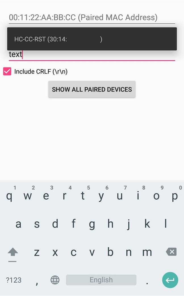
The SDK for developing plugins makes the task very straightforward. First, you need to create one Activity class (and of course the associated layout) that takes care of setting the parameters to be stored and used upon invocation. For my plugin, this meant the message to send, as well as the MAC address of the (paired) Bluetooth device. Though it wasn't necessary, to make the activity more user-friendly, a ListPopupWindow can present all the paired devices to the user, and auto-complete the MAC entry upon selection. The second class to create is basically a Broadcast Receiver class that gets called when the Task fires. In this case, it simply opens a connection to the device given by the saved MAC (if they have been paired in the past), and sends the desired message. As a side-note, I believe there is a small bug in the SDK, which I have reported here, and will update the post/code to reflect the outcome. [UPDATE: This commit fixed the issue.]
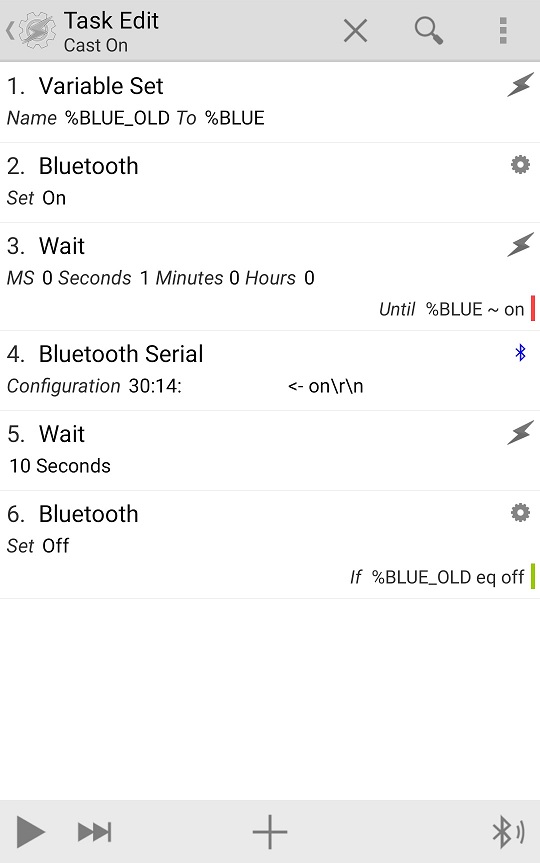
The interface (with the listing of all paired devices) can be seen in the picture below to the left (with the MAC address partially blocked), while the picture below to the right shows the complete Task used to turn the Chromecast on. The Task to turn Chromecast off is identical, except for the message payload. Note the delay before turning Bluetooth back off (if necessary) to allow plenty of time for a connection and data transmission.
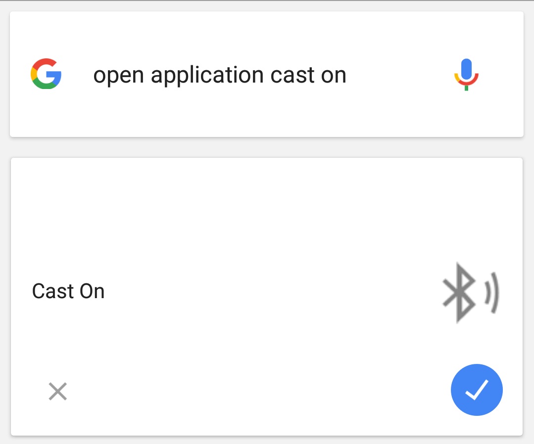
The final step was to turn the Tasks into standalone apps (that don't even require Tasker afterwards) using the Tasker App Factory. The benefit, besides the fact that the apps are the one-click solution that I was going for, is that I can now use Google Now to open them, for a zero-click solution:
Conclusion
In conclusion, I finally have an effective way to turn off my Chromecast from my phone thanks to Bluetooth, Arduino, and the Tasker plugin I wrote. Per usual, if you want to try any part of the code for yourself, feel free to dig around the GitHub repository. And until the next post, "OK, Google. Open Application Cast Off"!

