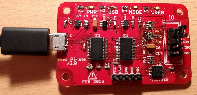
Building a Bus Pirate v3.8
Posted 2016/02/09. Last updated 2016/02/09.
Introduction
Dangerous Prototypes, the makers of the Bus Pirate and other really cool devices, run multiple giveaways a week, where they send you unpopulated PCBs of their projects for you to complete. I recently won a Bus Pirate v3.8 PCB, so this post is a summary of my adventure in building it, from buying the components and soldering, to programming and testing it under Linux.
Sourcing Parts in the UK
The official partlist links to Mouser, but here in the UK, I particularly like Farnell, since they have free next day delivery on any order placed online. Since I couldn't always find the exact same component, I tried to find alternative options that conform to the same standards (wattage, tolerance, etc.) and are more easily accessible or cheaper, so I ended up making a few substitutions. For instance, instead of the MIC5205 regulators by Micrel, I used the TC1185 by Microchip, substituted Red LEDs by Green, and used male pin headers instead of a shrouded header. As a side-note, make sure to buy a legitimate FT232RL chip by FTDI, because otherwise you may run into trouble with drivers (as we have seen both in 2014, and in 2016)! The table below is a list of components that I used, but I take no responsibility if they don't work for you, or if you find cheaper/better alternatives elsewhere.
| Name | Value | Description | Size | Links |
|---|---|---|---|---|
| C1-C6 | 0.1μF | Ceramic Capacitor | 0603 | Farnell |
| C7-C9 | 1μF | Ceramic Capacitor | 0603 | Farnell |
| C10-C11 | 10μF | Tantalum Capacitor | 1206 | Farnell |
| IC1 | PIC24FJ64GA002 | Microcontroller | SSOP28 (208mil) | Farnell, Microchip |
| IC2 | FT232RL | USB to UART | SSOP28 (208mil) | Farnell |
| IC3 | 74HC4066 | Quad Analog SPST Switch | TSSOP14 | Farnell |
| J1 | - | Micro USB Type B | - | Ebay |
| L1 | 700mA+ | Ferrite Bead | 0805 | Farnell 1, Farnell 2 |
| LED1-4 | - | LED | 0603 | Farnell |
| R1, R5 | 2kΩ | Thick Film Resistor | 0603 | Farnell |
| R2-R4, R6 | 1.1kΩ | Thick Film Resistor | 0603 | Farnell |
| RN1-RN3 | 10kΩ | Resistor Array | 0603 | Farnell (Convex), Farnell (Concave) |
| VR1-VR2 | TC1185-3.3V | Low Dropout Regulator | 5/SOT-23 | Farnell, Microchip |
| VR3 | TC1185-5V | Low Dropout Regulator | 5/SOT-23 | Farnell, Microchip |
| I/O, ICSP | 15 pins | Male Headers | 2.54mm | Ebay |
Soldering SMDs
Though there are plenty of good tutorials on soldering SMDs (e.g. here, here, and here), my soldering iron is not particularly great and I do not have the appropriate tip, so the end result was not particularly ideal. After securing the PCB onto a holder, I decided to tackle the ICs and the USB first, then the regulators and the resistor arrays, and then all other components. My approach for the ICs was to use flux and leave some solder on the pads of the PCB, solder two opposing pins, and then do the rest. For that, I decided to go with the "bridge all pins together" technique, but instead of dragging out the remaining solder, I used solder wick to remove the excess solder. In general, I'd have to say that it went pretty well, especially considering my lack of experience with SMDs and the equipment at hand, with one exception. For one of the resistor arrays, there was a bridge that I could not remove no matter how hard I tried, and due to the persistent heat, the pad broke.
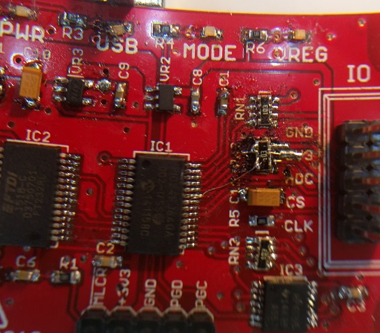
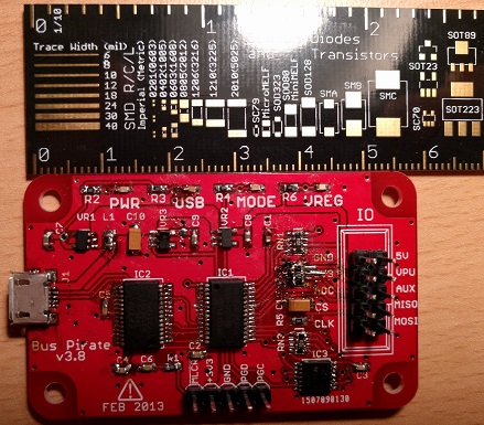
I went back to the PCB and schematic images, and it turned out that this bridge was an actual connection that was present on the PCB... The solution was to take a single strand of wire and connect the two parts of the resistor array with a single pin on the IC. This wasn't particularly easy, but in the end it worked (picture below and left)! I double checked all the connections with the multimeter, and I was convinced that the PCB was ready, though perhaps needing some cleanup (picture below and right).
Burning the Bootloader under Linux
The next step was to burn the bootloader onto the Bus Pirate. Though I have found a couple of good resources for this already (1 and 2), I needed to modify a few steps as I was running Linux (also, the second link is in Spanish, so repeating some of what it says in English is probably a good thing). Though I already owned a PICkit 3, I hadn't yet used it, as I tend to work with Atmel chips, so I first had to install the toolchain.
This meant downloading the installer, but before the usual untaring, chmoding, and running under sudo (also described here), I needed to install 32-bit dependencies on my 64-bit Debian-based system. This meant running sudo dpkg --add-architecture i386 to add the architecture, and then sudo apt-get update to update the repositories. The IDE depends on some extra libraries (see here), but the ones I was missing could be installed via sudo apt-get install libx11-6:i386 libxext6:i386 libexpat1:i386. After the dependencies, the MPLAB X installation went without a hitch.
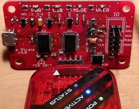
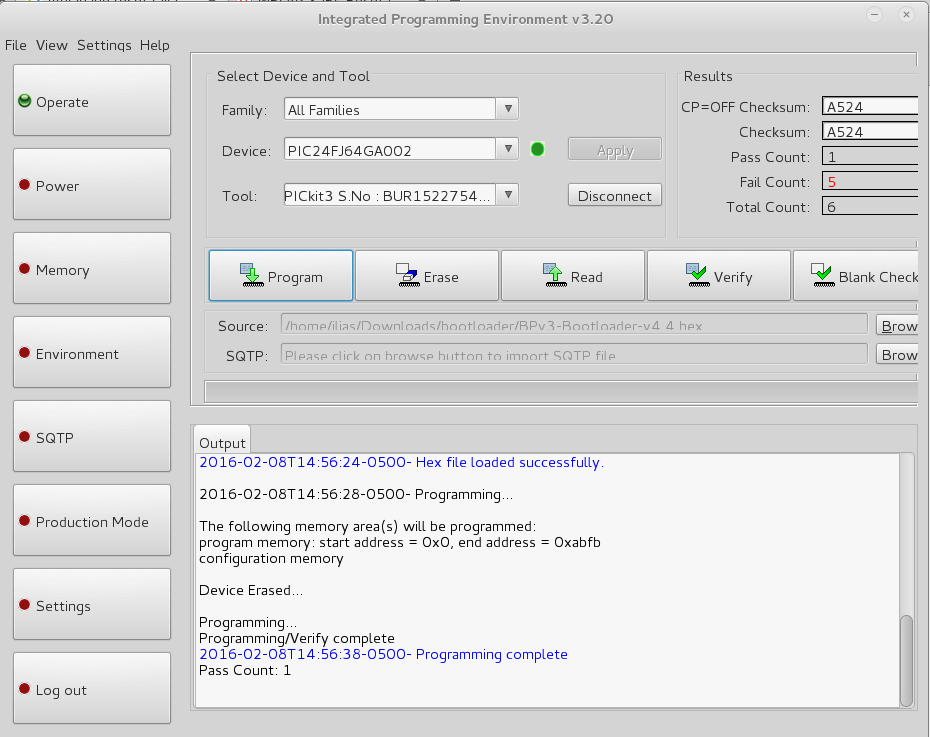
To actually program the Bus Pirate, we need to download the bootloader. After opening the MPLAB IPE (and not the IDE) and entering Advanced Mode, we need to enable the "Power Target Cicruit from Tool" option under the "Power" side-menu option. Then, going back to the "Operate" menu, we select PIC24FJ64GA002 as the "Device", and connect the PICkit 3 to the ICSP header, by joining the two arrows at the MLCR pin, and leaving the 6th pin in the PICkit 3 empty, as seen below and to the left. If the connections are correct, the device should be recognized when we click the "Connect" button. After pointing the "Source" field to the downloaded bootloader hex file (via the "Browse" button), we can click on the "Program" button to upload the binary to the device. If everything goes well and the hex file uploads successfully, the output should look like the one below and to the right.
Programming the Firmware and Testing under Linux
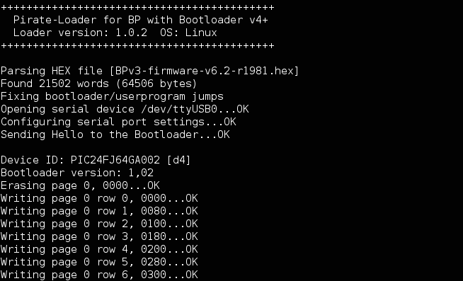
With the bootloader on the device, we no longer need the the PICkit 3, so we disconnect it, and connect the Bus Pirate to the PC via the micro USB cable. We need to grab the firmware along with associated utilities. In my case, I accidentally went with the r1981 firmware instead of the latest r2151 revision, but the discussion remains the same. For Linux, I used the pirate-loader_lnx tool (don't forget to chmod!) instead of the GUI. We need to place a jumper between PGD and PGC, and then we can program the firmware by issuing the simple command ./pirate-loader_lnx --dev=/dev/ttyUSB0 --hex=BPv3-firmware-v6.2-r1981.hex, where of course you should change the dev and hex file names to correspond to your setup. If everything goes according to plan, you should start seeing output similar to this one:
Performing a Self-Test
After the firmware is uploaded onto the device, remove the jumper and the USB cable, and plug the cable back in. The next step is to ensure that the Bus Pirate behaves as expected via a self-test. Connect to it via the screen /dev/ttyUSB0 115200 command, and enter i to get information about the device. If this cursory level of communication works, add two jumpers, one between the 5V and VPU pins, and one between the 3V3 and ADC pins, as shown below.
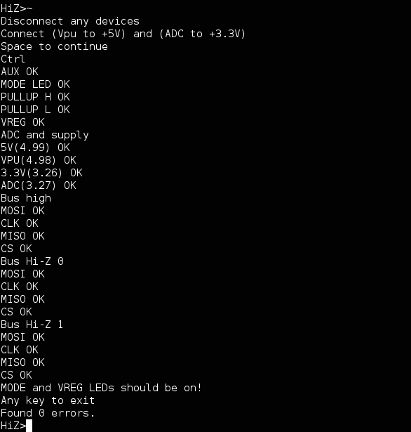
Then enter ~, and press space on the prompt. If everything works correctly, the output should be like the one below, and the MODE and VREG LEDs should be on (as in the picture above). If something does not work, it's probably due to soldering, and this guide goes over what you should check in case any of the tests fail. Otherwise, congratulations, you have just built a working Bus Pirate!
Conclusion
Overall, this was certainly a great exercise in soldering, where I definitely have a lot to improve. The Bus Pirate seems like a great device, with many capabilities (I already tried it on the 1-Wire protocol successfully), but it is very unfortunate that documentation is so scattered, and development seems to have ceased. Be that as it may, I am looking forward to integrating it in my toolset, and, of course, to my next PCB build!
