Fixing LVDS Cables for CCFL LCD Screens
Posted 2015/07/01. Last updated 2019/02/20.
Introduction
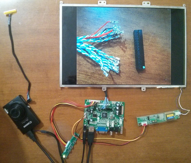
Recently, I dismantled a couple of really old laptops, and thought I'd try to reuse their screens by turning them into external monitors. There are already many good tutorials explaining how to find a suitable controller for your screen (i.e. dismantle your laptop, find the screen model number, and ask the seller for the right board), so I will skip this part and focus on the screens and the cables instead.
The screens models were AU Optronics B150XG01 V.2 and LG LP154W01-TLB5, which despite having different sizes and resolutions both use 1 CCFL bulb, and have a 30 pin connector. CCFL stands for Cold Cathode Fluorescent Lamp indicating that the screen backlight does not use a Light-Emitting Diode (LED), but instead a (single, in this case) bulb which requires an inverter to output over 1.1-1.4 kV for the lamp's ignition. However, just ordering a 30 pin cable and assuming that it works turned out to be the wrong thing to do: the controller came with a 30-to-20 pin cable which worked fine, but the additional 30-to-30 pin ones I ordered (before receiving the controller) did not work at all. I set out to fix the cables I bought, and in the process I learned a decent bit about how they work, so I wrote-up this post to help anyone that may run into similar issues in the future.
Low-Voltage Differential Signaling
It turns out that these screens use a standard called Low-Voltage Differential Signaling (LVDS) that conveys information through the polarity of the voltage differential ΔV (a few hundred mV) between 2 wires. The two wires must have the same length and are twisted together to reduce susceptibility to Electromagnetic Interference (EMI). Though these details are not important for this project, further information can be found here and here.
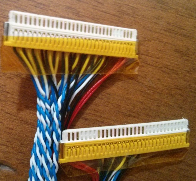
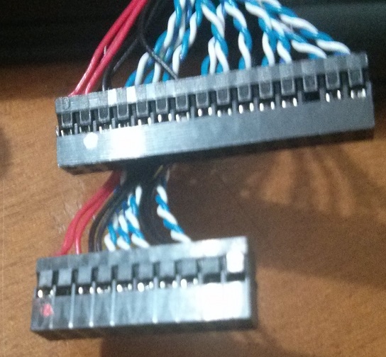
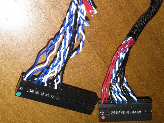
The controller I bought came with a Fix-30P-D6 LVDS cable, but I accidentally ordered a Fix-30P-S8 cable, which unfortunately turn out to not be compatible (and whose names I didn't know at the time). In the pictures that follow, the S8 is shown at the top and the D6 at the bottom:
In these cables, blue wires correspond to negative differential inputs, white wires to positive differential inputs, while red and black are VCC and GND per usual. As seen above, the two cables have different pinouts (for instance, look at the red wires), which explains why the S8 cable did not work.
The Connections
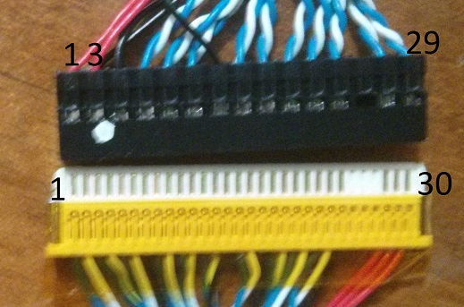
Before looking at any theoretical aspects, I decided to first try and map out the connections of the two cables. Specifically, we number as 1 the leftmost pin of the LCD cable end and by the normal alternating way the 2x15P socket:
I used my multimeter to test the connections of the two cables and created the following mapping:
| LCD | D6 | S8 | LCD | D6 | S8 | LCD | D6 | S8 |
|---|---|---|---|---|---|---|---|---|
| 1 | 4 | 7 | 11 | 9 | 18 | 21 | NC | 28 |
| 2 | 1 | 8 | 12 | 10 | 19 | 22 | NC | 29 |
| 3 | 2 | 9 | 13 | 6 | 20 | 23 | NC | 30 |
| 4 | NC | 10 | 14 | 11 | 5 | 24 | NC | 13 |
| 5 | NC | 11 | 15 | 12 | 21 | 25 | NC | NC |
| 6 | NC | 12 | 16 | 13 | 22 | 26 | NC | NC |
| 7 | NC | 4 | 17 | 15 | 6 | 27 | NC | NC |
| 8 | 7 | 15 | 18 | 16 | 23 | 28 | NC | 1 |
| 9 | 8 | 16 | 19 | 14 | 24 | 29 | NC | 2 |
| 10 | 5 | 17 | 20 | NC | 27 | 30 | NC | 3 |
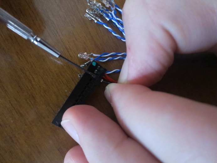
Then by carefully lifting the socket tabs of the S8 as shown below, and by using the above table, I was able to re-wire the S8 cable to match it counterpart.
As shown above, this meant that the coloring was no longer valid, that not all pairs were twisted together, and that I had to cut some of the other wires. This was not an ideal solution, and it would have been better if I had re-wired both ends and removed extra cables, but it actually worked!
Looking at the Datasheets
Now that I fixed the cable, I wanted to know a little bit more about the operation and incompatibility of the connections. I looked at the datasheet of my A.VST29.01B controller and reproduced the 2x15P connector interface in the table below:
| PIN | SYMB | PIN | SYMB | PIN | SYMB |
|---|---|---|---|---|---|
| 1 | VCC | 11 | O2- | 21 | E1- |
| 2 | VCC | 12 | O2+ | 22 | E1+ |
| 3 | VCC | 13 | GND | 23 | E2- |
| 4 | GND | 14 | GND | 24 | E2+ |
| 5 | GND | 15 | OC- | 25 | GND |
| 6 | GND | 16 | OC+ | 26 | GND |
| 7 | O0- | 17 | O3- | 27 | EC- |
| 8 | O0+ | 18 | O3+ | 28 | EC+ |
| 9 | O1- | 19 | E0- | 29 | E3- |
| 10 | O1+ | 20 | E0+ | 30 | E3+ |
The notation is such that O stands for "Odd", E for "Even", C for "Clock", while + and - the positive and negative of the differential inputs. Looking at the mappings again, we can see that the cable connects to the odd clock and odd pairs 0-2. Indeed, the screen datasheets confirm the pinouts, but this does not quite explain what even and odd mean, or why the cables are different.
However, a fantastic white paper by Intel explains all the intricacies. I won't go into too much detail, since the explanations are well-written and easy to follow, but the idea is that pixels are transmitted in 7-bit (serial) outputs per wire pair. Older screens like mine transmit 18 bits of RGB values (18-bpp) plus 3 bits of timing data per 7-bit transmission, thus needing 3 data pairs (plus the clock pair). A fourth pair may be used to transmit another 6 bits of RGB data (24-bpp), which contain the 2 low-order bits from each color channel, making these connections backwards-compatible. The problems, however, arise from the dual-channel (parallel) configurations, which are used to double the transmission rate. These transmit the odd pixel data from the first ("odd") set of pairs and the even pixels using the second ("even") set of pairs, regardless of the number of bits per pixel. Though it is unclear why the connectors themselves are not backwards-compatible, even if they were, the display would not be driven correctly.
Conclusion
In conclusion, I would like to warn others to not just look at the connector and lamp type of their screen, but also at the signal interface, and the data voltage (which in my case was 3.3V, but can be 5V or 12V), both of which can be found in the screen's datasheet. And now that I have verified that both screens are working and that I did not accidentally fry them, I have to figure out a nice and effective way to mount them...
